Test yourself on Truth Tables with exam style questions, marked instantly.
Flashcards that come back just before you would forget them.
A revision plan that remembers what you know and shows what to do next.
See which topics you have nailed and which need another look.
Quiz yourself on Truth TablesGet your flashcardsBuild my revision planTrack my progressBuilding Complex Decisions
Truth Tables Reference
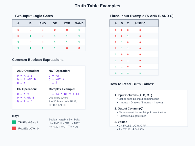
Deep Dive: From Simple Gates to Complex Circuits
Individual logic gates are the building blocks, but real computing power comes from combining them into circuits. Think of it like LEGO bricks - one brick is just a shape, but connect thousands together and you can build anything from a house to a spaceship.
A modern CPU contains billions of transistors arranged into logic gates, which are then connected into complex circuits. The Intel i9 processor has over 10 billion transistors! Each one helps make tiny binary decisions that, when combined, let you watch videos, play games, and run complex calculations.
Why this matters: Understanding how to combine gates and work through logic circuits step-by-step is essential for computer architecture, programming conditional logic, and debugging digital systems.
Working Through Combined Logic Circuits
When you encounter a combined logic circuit, follow this systematic approach:
Step 1: Identify All Inputs
- Label each input signal (typically A, B, C, D...)
- Count them to determine truth table size: n inputs = 2ⁿ rows
- Example: 2 inputs = 2² = 4 rows; 3 inputs = 2³ = 8 rows
Step 2: List All Input Combinations
- Create truth table with columns for each input
- List combinations in binary order: 000, 001, 010, 011, 100, 101, 110, 111
- This ensures you cover every possible scenario
Step 3: Work Left to Right Through Circuit
- Start at the inputs on the left side
- Move toward the final output on the right
- Process each gate in sequence
Step 4: Calculate Intermediate Outputs
- Add columns for intermediate gate outputs
- Label them clearly (e.g., "A AND B", "NOT C")
- Calculate values for ALL input combinations
Step 5: Calculate Final Output
- Use intermediate results to get final output
- This is your last column in the truth table
- Double-check each row for accuracy
Example 1: (A AND B) OR C
This circuit has TWO gates: First an AND gate combining A and B, then an OR gate combining that result with C.
| A | B | C | A AND B (intermediate) |
(A AND B) OR C (final output) |
| 0 | 0 | 0 | 0 | 0 |
| 0 | 0 | 1 | 0 | 1 |
| 0 | 1 | 0 | 0 | 0 |
| 0 | 1 | 1 | 0 | 1 |
| 1 | 0 | 0 | 0 | 0 |
| 1 | 0 | 1 | 0 | 1 |
| 1 | 1 | 0 | 1 | 1 |
| 1 | 1 | 1 | 1 | 1 |
Intermediate column (A AND B): Only shows 1 when BOTH A and B are 1 (row 7 and 8)
Final output: Shows 1 when EITHER the intermediate is 1 OR C is 1 (rows 2, 4, 6, 7, 8)
In plain English: Output is 1 if "A and B are both true" OR "C is true"
Example 2: NOT(A) AND B
This circuit inverts input A (using NOT gate) then combines it with B using an AND gate.
| A | B | NOT A (intermediate) |
NOT(A) AND B (final output) |
| 0 | 0 | 1 | 0 |
| 0 | 1 | 1 | 1 |
| 1 | 0 | 0 | 0 |
| 1 | 1 | 0 | 0 |
NOT A column: Flips A's value (0→1, 1→0)
Final output: Only 1 when NOT(A) is 1 AND B is 1 - that's row 2 only
In plain English: Output is 1 only when "A is false AND B is true"
Visualizing Circuit Flow: (A AND B) OR C
Truth Table Size Reference
The number of rows in a truth table depends on the number of inputs:
| Number of Inputs | Formula | Number of Rows | Example Combinations |
|---|---|---|---|
| 1 | 2¹ | 2 | 0, 1 |
| 2 | 2² | 4 | 00, 01, 10, 11 |
| 3 | 2³ | 8 | 000, 001, 010, 011, 100, 101, 110, 111 |
Memory trick: Each input DOUBLES the number of rows. 1 input = 2 rows, 2 inputs = 4 rows, 3 inputs = 8 rows.
Order of Operations in Logic Circuits
Just like mathematics has BIDMAS/PEMDAS, Boolean logic has an order of operations:
| Priority | Operation | Example |
|---|---|---|
| 1st (highest) | Brackets / Parentheses | Evaluate (A OR B) before anything else |
| 2nd | NOT | NOT(A) is evaluated before AND/OR |
| 3rd | AND | A AND B is evaluated before OR |
| 4th (lowest) | OR | OR is evaluated last |
Example: NOT(A) AND B OR C
- Step 1: Calculate NOT(A)
- Step 2: Calculate NOT(A) AND B
- Step 3: Calculate [NOT(A) AND B] OR C
Exam Tips - Combined Logic Circuits
When completing truth tables:
- Always show intermediate columns - you'll get method marks even if final answer is wrong
- Work systematically - do ALL rows for one column before moving to the next
- Label intermediate columns clearly - write what they represent (e.g., "A AND B")
- Double-check: Count your rows - 2 inputs = 4 rows, 3 inputs = 8 rows
Common mistakes to avoid:
- Skipping intermediate steps - always show your working!
- Getting the gate order wrong - work LEFT to RIGHT through the circuit
- Confusing brackets: NOT(A AND B) is DIFFERENT from NOT(A) AND B
- Missing rows in truth table - always use 2ⁿ rows for n inputs
Quick evaluation tips:
- Brackets first: Like in maths - evaluate expressions in brackets before anything else
- NOT next: Apply all NOT operations before AND/OR
- AND before OR: Just like × before + in maths
- Left to right: When same priority, work left to right
Make this stick
Signing in gives access to all PrepWise features.